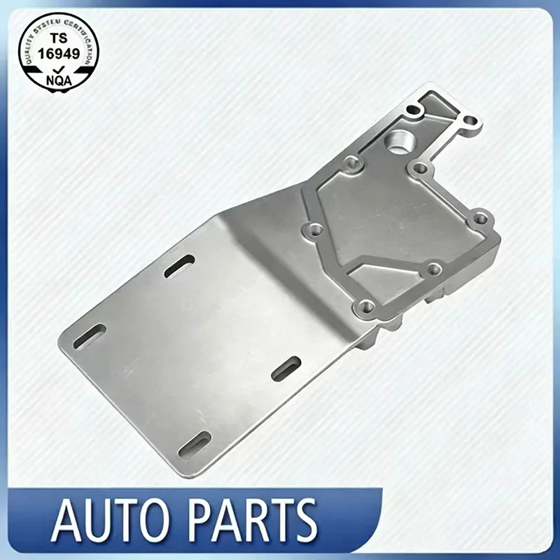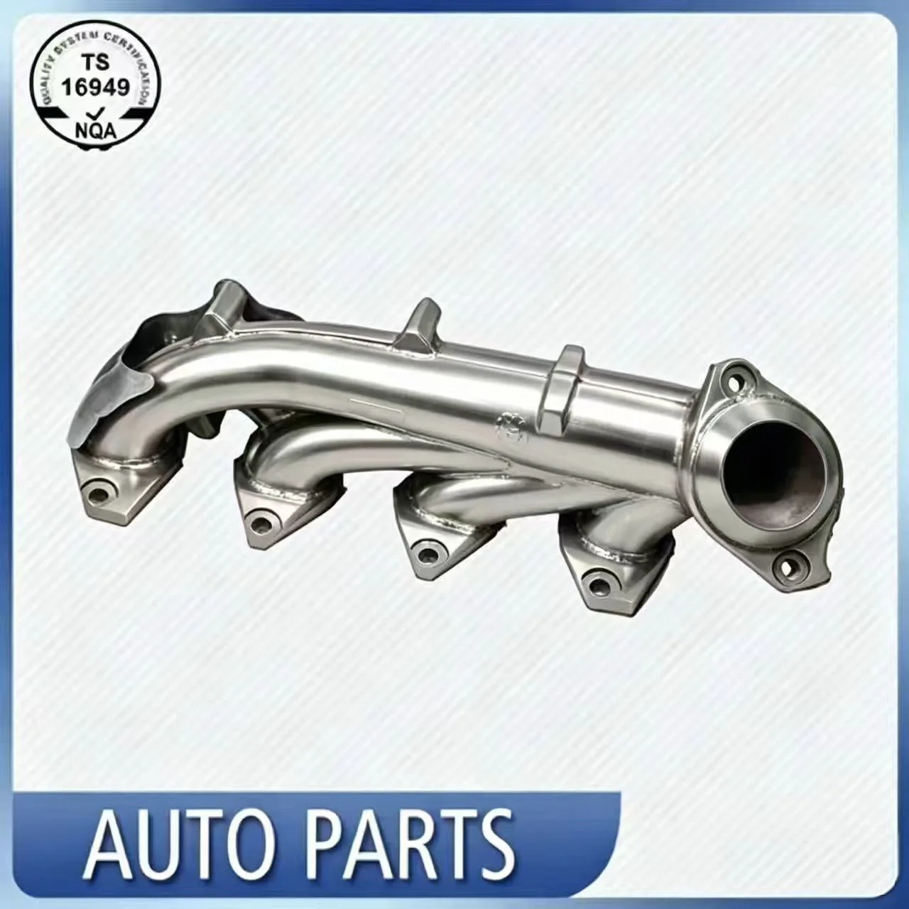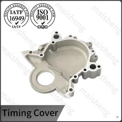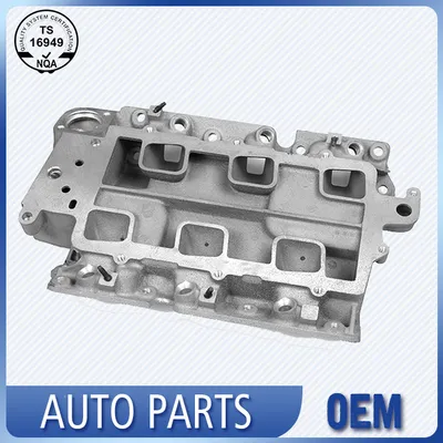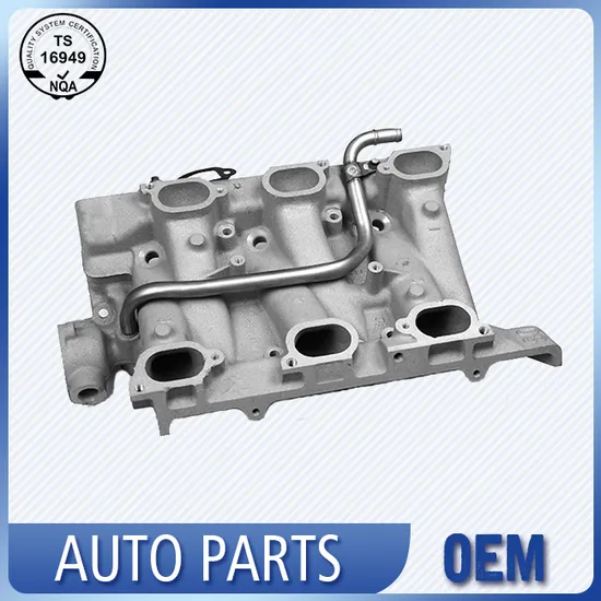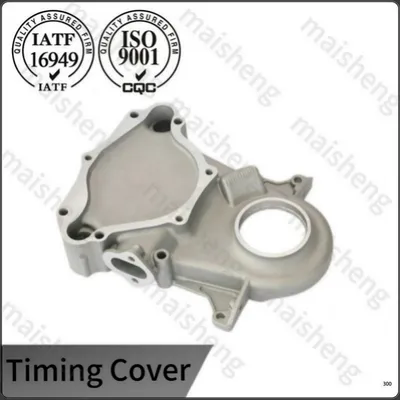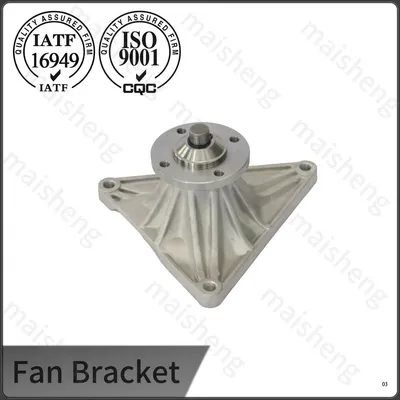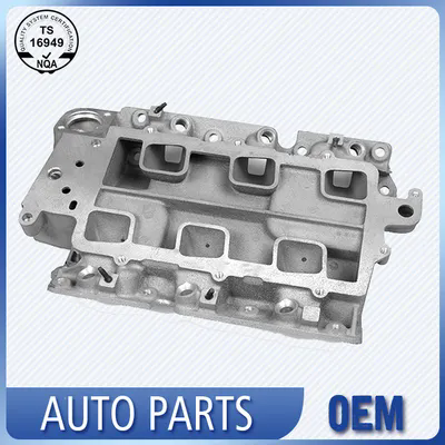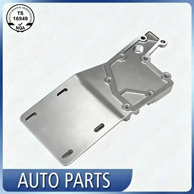

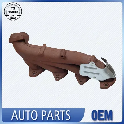
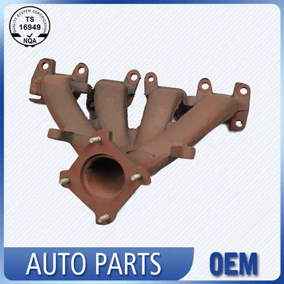
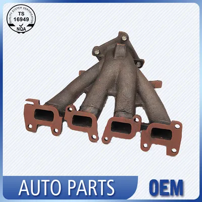
Our Cast Iron Exhaust Manifold Series covers a wide range of configurations, including 3-cylinder, 4-cylinder and V-type designs, to fit most passenger vehicles, light trucks and commercial engines. Each manifold offers excellent thermal conductivity and crack resistance under extreme operating temperatures.
Designed with optimized internal runners, these manifolds ensure balanced exhaust gas flow, reducing backpressure and improving engine efficiency. Reinforced flanges and thick-walled construction prevent warping and leaks over extended use. All units are dimensionally inspected and pressure-tested to meet OE fit and performance standards, making them reliable replacements for both fleet maintenance and individual repairs.
|
Model NO. |
IP662 |
Certification |
ISO9001, TS16949 |
|
Type |
Exhaust Pipe |
Transport Package |
Bulk Packaging |
|
Body Material |
Alloy |
Service |
Custom |
|
Component |
Exhaust Pipe |
Origin |
China |
|
Trademark |
OEM |
Production Capacity |
2000 Pieces/Week |
|
Specification |
Custom |
|
|
Cast iron exhaust manifolds excel in thermal stability and fatigue resistance for high-load engines. Their dense construction evenly dissipates heat, reducing hotspots while maintaining consistent exhaust flow to support turbo response and emissions control. Engineered for direct-fit compatibility, they eliminate costly modifications, offering reliable, low-maintenance performance for engine rebuilds and fleet upgrades.
The iron chemistry is formulated to produce Type A flake graphite evenly dispersed in a pearlitic matrix, a combination that yields a thermal conductivity close to 50 watts per meter kelvin at 200 degrees Celsius. This level of heat transfer moves thermal energy rapidly from the port walls into the collector body, smoothing out temperature gradients that would otherwise concentrate stress near the flange joints. The graphite flakes also serve as internal strain absorbers; when the manifold cycles between ambient and exhaust gas temperatures exceeding 700 degrees Celsius, microscopic deformation localizes at the graphite tips rather than advancing into continuous crack networks. Each melt is evaluated with a chill wedge test and a spectrographic analysis, confirming that carbon equivalent and silicon content stay within narrow bands to maintain consistent graphite form.
Manifold shells are shaped in resin bonded sand molds that are designed with a pressurized gating system to keep metal velocity low and reduce sand erosion. After pouring and shakeout, the raw castings pass through a continuous normalizing furnace at 880 degrees Celsius. This step dissolves carbides that may have formed during cooling and rebuilds a uniform pearlitic structure, yielding a hardness envelope of 180 to 220 HBW across the entire part. Following normalizing, the flanges are machined flat and the port openings are finished to a controlled surface roughness below 6.3 micrometers Ra. The last thermal operation is a low temperature stress relief at 550 degrees Celsius for three hours, which relaxes the residual strains introduced by foundry cooling and heavy milling cuts, leaving the component dimensionally stable during its first thermal cycles on the engine.
Flange flatness is verified on a granite surface plate using a dial indicator zeroed at three corner points, with an acceptance limit of 0.15 millimeter across the sealing face. Port positions relative to the datum holes are captured on a bridge type coordinate measuring machine for at least three samples per shift, ensuring that the runner alignment matches the engine head within a 0.3 millimeter tolerance zone. Each completed manifold is then clamped onto a leak test fixture, pressurized to 1.5 bar with shop air and submerged in a water tank. Any continuous stream of bubbles triggers immediate quarantine and root cause review. For turbocharger applications, a supplementary hot leak test at 250 degrees Celsius is performed on a periodic basis using a helium tracer, verifying that the thermal expansion of the cast body does not open microvoids at the collector joint.
The entire production sequence runs within an IATF 16949 certified facility that has specialized in cast and machined automotive parts for more than 25 years. Each heat of iron is assigned a unique lot number that appears on the delivery note and is linked to the corresponding spectrometer record, sand test report and heat treatment chart. Finished manifolds are marked with a permanent ink code that references this lot, allowing full backward traceability even after years of field service.
When an OEM customer requires a Production Part Approval Process submission, we supply a level 3 dossier that contains the process flow diagram, a failure mode and effects analysis, capability indices for critical dimensions and the material certificate from the foundry laboratory. This package gives engineering teams the data they need to validate the manifold for their specific engine platform.
Premium cast iron exhaust manifolds engineered for durability, thermal stability, and optimized exhaust flow.
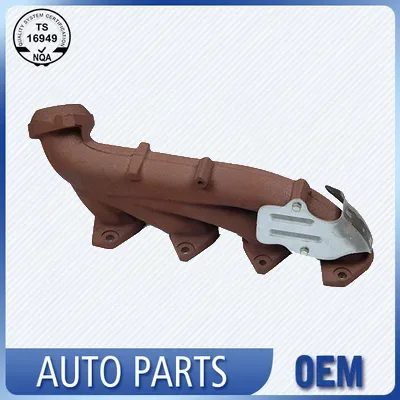
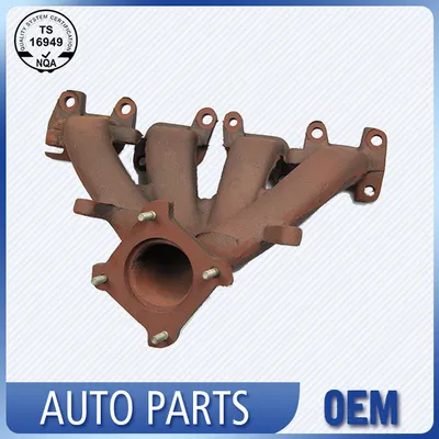
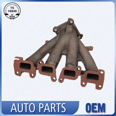
1.What vehicles and engines are cast iron exhaust manifolds applicable to?
A: It matches heavy-duty diesel trucks, engineering machinery, agricultural equipment, large-displacement commercial vehicles, old-school gasoline engines and turbocharged heavy-load engines. It is specially designed for working conditions with ultra-high exhaust temperature, long-time full-load operation and severe vibration, where thin steel manifolds are prone to deformation and cracking.
2. What are the main causes of cracking and air leakage of cast iron exhaust manifolds?
A: Frequent cold-hot thermal cycling produces huge thermal stress to form fatigue cracks; improper over-torque installation damages flange structure; missing or damaged heat shield leads to local ultra-high temperature burning; long-term use of inferior thin gaskets causes uneven stress on flange; external impact during maintenance or off-road driving creates hard cracks.
3. How does the factory confirm that every manifold meets OE specifications before shipment?
A: A four stage release gate is applied. First, raw iron chemistry is verified against the melt card. Second, after heat treatment, a hardness test and a random microstructural check are performed. Third, machined dimensions are measured on a sampling plan based on the lot size. Finally, every piece undergoes the water immersion leak test described above, and the result is recorded. A packing inspector then matches the unit against the customer part number and visually confirms surface condition. This layered approach ensures that dimensional, material and sealing requirements are satisfied before the product leaves the dock.
Address
NO.556,Kangzhuang South road, Jiangbei District,Ningbo City, Zhejiang China
Tel
If you have any enquiry about quotation or cooperation, please feel free to email us at huyanping@nbmachinery.com or use the following inquiry form.Our sales representative will contact you within 24 hours. Thank you for your interest in our products.